A Firm Foundation of Quality and Reliability
Since 1912, Chance® has engineered and manufactured industry-leading deep foundation solutions in Centralia, Missouri. Our helical piles and anchors have been specified for more jobs than any other helical pile brand and are still going strong.
Find a Distributor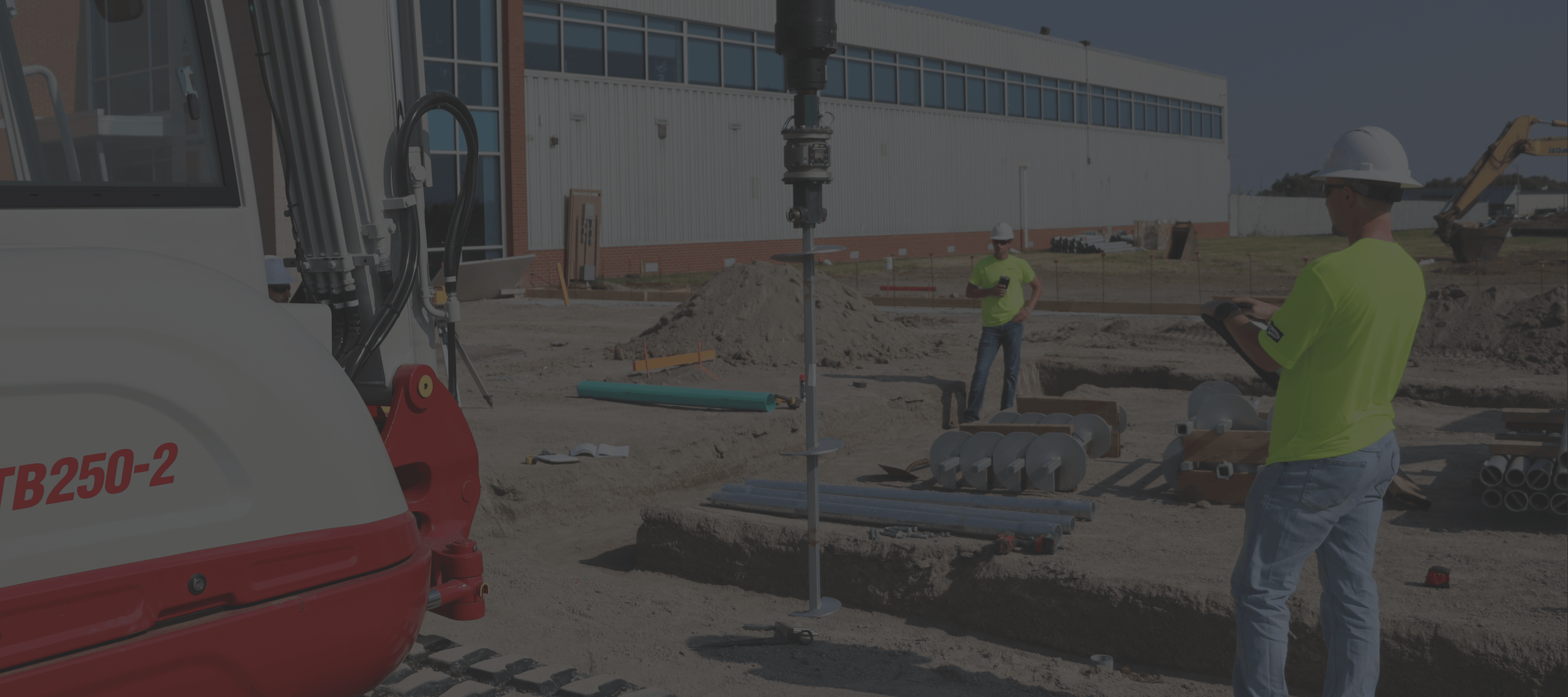
Why Chance Foundation Solutions
As the industry pioneer of helical anchors and piles, our company is built on a deep foundation of trust and expertise.
Local foundation experts comprising the largest distribution network in North America
Engineered for dependability and long-term stability in a broad range of applications
Helical piles made with traceable prime mill-direct steel, engineered and manufactured in America
Deep Foundation Products and Tools
We design, create, and implement deep foundation systems built to fit any application. Explore our product categories to find a solution that meets your needs.
Experts in Foundation Solutions
At Chance, we offer a wealth of resources to help you navigate all your foundation projects. Dive into our library of technical literature, certifications, and educational resources to discover what makes us a leader in the foundation industry.
The Industry-Leading Deep Foundation Solution
When you choose Chance helical piles, you can trust they are designed by technical experts, made with high-quality materials, and backed by unrivaled customer support.
Browse all VideosVersatile Foundations for Varied Applications
From high-capacity new construction applications supporting up to 220,000 pounds per pile to limited access remediation, Chance products will ensure the long-term stability and safety of your structure.
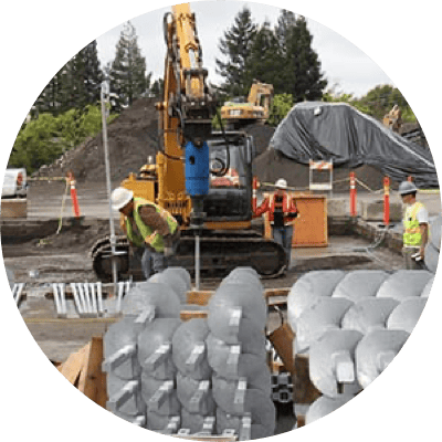
New Construction
Enjoy faster installation, low mobilization costs, and immediate loading with a proven deep foundation for new construction projects.
Learn More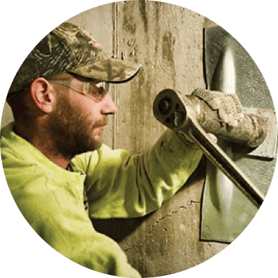
Residential
Protect your home with foundation stabilization, wall repair, or disaster recovery designed for both new construction and remediation projects.
Learn More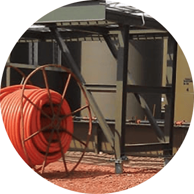
Oil/Gas Pipeline
Upstream, midstream, and downstream: helical piles provide strong foundations for stabilization needs for oil production, transportation, and processing.
Learn More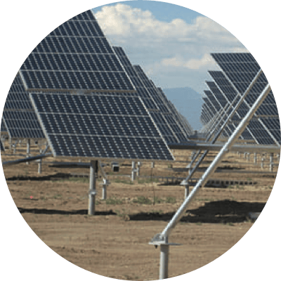
Solar & Wind
Site-specific solar panel and wind turbine foundations are engineered for quick installation and durability in a variety of environments.
Learn More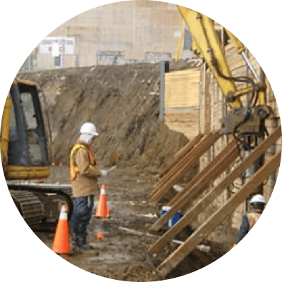
Earth Retention
Our helical tiebacks and Soil Screw® anchors provide necessary support for slopes, cuts, and retaining wall designs.
Learn More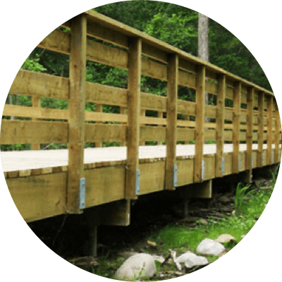
Boardwalk Walkways
Our helical piles keep boardwalks secure and accessible for visitors while minimizing disturbance to the surrounding environment.
Learn More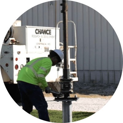
Pole Base Foundations
A base with excellent lateral capacity for applications such as streetlights, communication infrastructure, and EV charging stations.
Learn More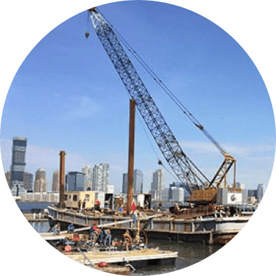
Marine
Sustainable, reliable, economical: helical anchors have a wide range of proven uses for boat owners, harbormasters, and marine construction and civil engineering firms.
Learn More